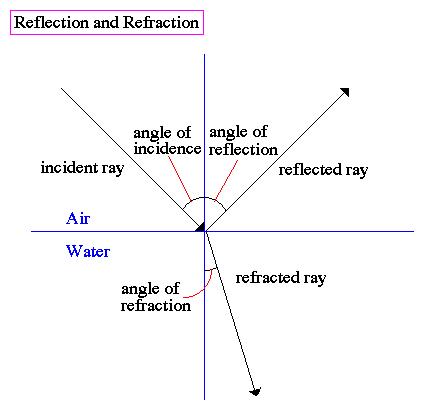
Introduction. When a ray of light strikes a flat (or planar) mirror, it will reflect (or be refused) from the surface according to a simple geometric law. We can easily discover this simple law, the Law of Reflection, and further reveal the features of image formation that occur in a planar mirror.
Materials.
 Metric ruler
5 cm x 20 cm rectangular mirror
4 cm x 10 cm x 5 cm rectangular wood block
35 cm x 50 cm sheet of 0.5 cm-thick styrofoam poster board
3 straight pins
2H pencil
3 (different) colored pencils
Double-sided tape
Protractor
Legal-size blank paper
Method.
1. Attach the wooden block to the center of the nonreflective side of the mirror using double-sided tape such that the mirror will stand vertical and upright when placed on the horizontal poster board.
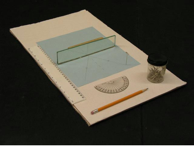
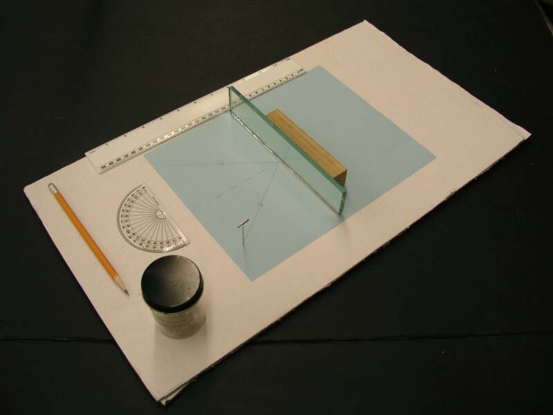
2. Place a sheet of legal-size paper in the center of the styrofoam poster board. Draw a line width-wise across the center of the paper. Set the block and mirror assembly such that the back (nonreflective) edge of the mirror rests along this line. Be mindful to keep the mirror in this orientation throughout the duration of the exercise (see pictures a and b below).
3. Assemble the three pins in the field of the mirror's view by pushing them through the paper and into the styrofoam board such that they are approximately 5 cm distant from one another. Draw three lines connecting the positions of the pins on the paper such that the resulting figure is a triangle. The pins, therefore, should occupy the vertices of the triangle. The images of the pins should be clearly visible in the mirror.
4. Using a metric ruler (or the Ray-Sight Method), locate the paths of three rays of light which are directed from each pin to the mirror and in turn reflected by the mirror to one of your eyes as you view the images from differing positions in the field of view.
Ray-Sight Method.
1. Given the fact that light rays travel in straight lines, we can align pins with their image in the mirror. This line is, in fact, the pathway of the incident ray of light traveling from the pin to the mirror.
2. We must locate at least three different reflected light rays from each pin by viewing the image of each pin and drawing a line from the position of the image at the mirror to an additional location in the field of view. This is accomplished by sighting along the surface of the paper with one eye and, while holding the pencil vertically, placing a dot on the sheet of paper over the apparent position of the pin. That is, place the pencil on the paper directly over the image of the pin. (In other words, you will be blocking the pin from view by placing the pencil directly between the image of the pin and your eye.)
3. Sketch three ray pairs (incident and reflected) for each pin by connecting the dot at the mirror with the actual and apparent position of the pin. Use colored pencils to differentiate among each of the three ray-pairs.
4. Once all nine pairs of rays have been sketched in colored pencil, remove the mirror from the paper. Construct a normal to the mirror surface line at each point of contact between the incident and reflected ray pair with the protractor. Then measure the angle of incidence and angle of reflection for each pair. Record your values in the data table provided. How do the angles for each ray-pair compare to one another?
5. Using the appropriate colored pencils, extend each of the reflected rays into the field behind the mirror, that is, into the nonreflective side. Place a dot where each of the three same-colored ray-pairs intersect. This should be done for each of the three (like-colored) ray-pairs. By extending the rays to where they seem to originate (behind the mirror) we can locate the image.
6. Connect each of the three points of intersection with a straight line using a regular pencil. This figure is the apparent position (and appearance) of the reflection of the original triangular arrangement of pins placed in the reflective field.
7. Replace the mirror along the original line. Alternately lift and lower the mirror from this position while viewing the reflected and constructed image. Both should appear to be located in the same place. How well did you "locate the image"?
Data Table.
Pin A Pair 1Pair 2 Pair 3
Angle of Incidence __________ _____
Angle of Reflection __________ _____
Pin B
Angle of Incidence _____ __________
Angle of Reflection _____ __________
Pin C
Angle of Incidence _____ __________
Angle of Reflection _____ __________
Questions.
1. How does light appear to travel?
2. State the Law of Reflection as applied to plane mirrors.
3. Describe the characteristics of the image formed in a plane mirror.
4. Describe an alternate method by which the image (the apparent position of the image)
can be located.
5. Images in planar mirrors also appear to have experienced rotation. Do you agree?
Explain why (or why not). If so, where would the axes of rotation be located?