Vector Analysis: The Graphical Method of Vector Addition
Laboratory No. 7
Rules and Methods in the Graphic Approach to Determining the Sum of Two or More Concurrent Vectors
Vocabulary
antiparallel: refers to two (or more) concurrent vectors that are acting on a body in opposite directions or orientations anti-parallel vectors are those which appear graphically as arrows pointing in opposite directions; the angle (acting) between antiparallel vectors is 180 degrees.
concurrent: refers to vectors which are acting on the same body (or point) at the same time.
displacement vector: the vector of distance plus direction; it is the sum of how far and in which direction a body has been moved from its start position to its final position; the net straight-line change in position of a body.
direction: the orientation of a vector with respect to an established system of geographic (azimuthal) or angular indices.
equilibrant: that vector which, when added to a system of concurrent vectors, produces a zero vector sum; a vector equal in magnitude to but opposite in direction to the resultant.
force vector: the combination of the amount of force applied to an object and the direction in which that force is applied.
graphical method of vector addition: the method by which vectors, represented by drawn arrows whose length is proportional to magnitude and direction is referenced to directional indices, are placed in a sequential "head-to-tail" chain, the sum of which is the arrow-line connecting the "tail" of the first drawn vector to the "head" of the last drawn vector.
magnitude: the numerical portion of a vector; in graphical terms, it is the length of the drawn vector, referenced to an established magnitude:length scale.
parallel: refers to two (or more) vectors which are acting in the same direction or orientation; parallel vectors are those which appear graphically as arrows pointing in the same direction; the angle (acting) between parallel vectors is 0 degrees.
resultant: the non-zero sum of a system of concurrent vectors, determined by the process of vector addition; it is that unique vector which results from the combination of concurrent vectors.
vector: a physical phenomenon which possesses both magnitude and direction, such as displacement, velocity, force, momentum, and impulse; it is conventionally represented as an arrow, the length of which is proportional to magnitude and whose orientation is referenced to some type of directional indices (angular or geographic).
velocity vector: the combination of an object's speed and direction
Adding Vectors to Form a Resultant
1. On a large sheet of paper, establish a magnitude:length scale and directional-angular indices that will provide you sufficient drafting surface area on which to construct your vectors. Your metric ruler is the preferred tool used to perform this function. The grid spacing on graph paper, if so provided, may alternately be used to establish your magnitude:length scale and orientation indices.
2. Draw your first vector from a point chosen so that all the drawn vectors will fit within the confines of your paper. The first vector should appear as a line whose length and direction have been drawn in accordance with your established scale and indices. The starting point is located at the "tail" of the vector. The end of the vector should be adorned with an arrow-tip, oriented in the direction of action. This is the "head" of the first vector.
3. Starting from the head of the first vector, construct the second vector following the same procedure used to construct the first vector. The starting point (tail) for this vector will be at the arrow-tip (head) of the first vector. The end of the second vector should also be adorned with an arrow-tip which points in the direction of its action. This is the head of the second vector. The graphical method of adding vectors is accomplished by drawing them in a sequential "head-to-tail" chain. Additional vectors may be added to each previously drawn vector in turn.
4. The order in which vectors are placed (added) is irrelevant. As long as all of the vectors are drawn to the appropriate length and direction, the sum (resultant) will be the same.
5. Once all of the concurrent vectors have been drawn, it is time to construct the resultant vector (or vector sum). This is accomplished by drawing a line from the tail of the first vector to the head of the last vector. An arrow-tip is placed at the end of the line, that is, at the head of the last vector drawn. This is the resultant (sum) of all the vectors you have drawn in the chain. Label this line R. Measure the length of this line with your ruler and reference it to your magnitude:length scale. This value is a measure of it's magnitude, that is, the amount of sum of the system of vectors. Finally, measure the orientation of the line with your protractor with reference to your directional indices, in degrees. This is the direction of the vector sum.
Problems
Solve the following vector problems graphically and mathematically. Show all work. Graphical solutions must include directional indices, magnitude:length scales, and conversion factors as well as sketches of how the vectors are acting as well as adding. Mathematical solutions must include all equations, appropriate units and highlighted answers expressed to the nearest tenth. Use graph paper to assist your graphical solutions.
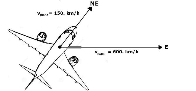
1. A bullet is fired due east from a gun mounted in an airplane traveling due northeast [see diagram below]. If the speed of the bullet is 600. km/h and the speed of the airplane is 150. km/h, what is the resultant velocity of the bullet?
2. Find the equilibrant of two 10.0-N forces acting upon a body when the angle between the forces is
a. 90 degrees
b. 120 degrees
c. 150 degrees
d. 180 degrees
3. A 60 km/h wind is blowing in a direction 30 degrees north of east.
a. What is the component of the velocity oriented to the east?
b. What is the component of the velocity oriented to the north?
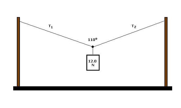
4. A horizontal wire is stretched between two vertical poles. When a 12.0-N weight is suspended at its center, the wire sags until the angle between its halves is 110 degrees [see diagram below]. What are the forces exerted by each half of the wire [T1 and T2] in supporting the weight?